Artificial Intelligence
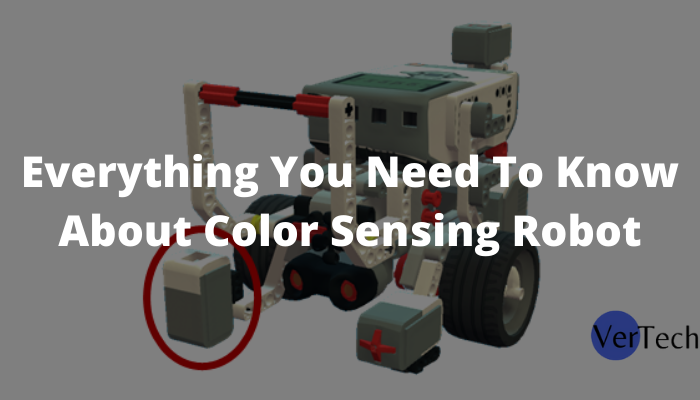
Everything You Need To Know About Color Sensing Robot

A camera is quite possibly the most impressive and exact sensor assuming that you know how to handle the pictures taken by it for the data you need. You can handle ensuing pictures and concentrate an assortment of data utilizing the picture Color Sensing Robot. MATLAB is an extremely amazing asset and assumes a significant part in picture handling.
Picture handling is changing over a picture into a computerized structure and playing out a few numerical procedures on it, to get an upgraded picture or to extricate some valuable data out of it. Most picture handling methods include regarding the picture as a two-layered signal and applying standard sign handling procedures to it.
Introduced here is a MATLAB-based project where pictures taken by the camera are handled for colors and the place of a red-hued object is removed from the picture. In light of the place of the red-shaded object in the picture, various information is sent by means of the COM port. The sequential information is gotten by the robot www.Roblox.con/redeem and it is done to compare development. You can change the code for any shading that you see as appropriate. This venture is only a model and you can involve this for different modern applications, for example, controlling weighty burden lifting machines with some object of a particular tone in your grasp.
Circuit and working
The circuit of the robot utilizes microcontroller P89V51RD2 (IC1) to get sequential information from the PC through driver IC MAX232 (IC3). The got information is investigated by the microcontroller IC1 and the engines are controlled through engine driver IC L293D (IC2). The power supply for the robot comes from a 9V battery which is directed to 5V by controller 7805 (IC4). 9V is additionally associated with pin 8 for IC2 for the engines.
Also, read Algebra Formula – Algebra in Everyday Life
The USB port of the PC is associated with the robot through a USB-to-chronic converter. Controlling orders to the robot are sent through the sequential port and the sign levels are changed over into 5V TTL/CMOS type by IC3. These signs are straightforwardly taken care of by two microcontroller IC1 for controlling engines M1 and M2 to move the robot every which way. Port pins P1.0 through P1.3 of IC1 are associated with the contributions of IN4 through IN1 of IC2, separately, to give driving information sources. EN1 and EN2 are associated with Vcc to keep IC2 empowered 100% of the time.
The application running on the PC deciphers the place of the shaded item and sends comparing orders to the robot through the sequential port. The Nerf Robot is was modified to push ahead on the off chance that it gets ‘a’ from the sequential port. Likewise, for different positions, the letters are recorded in the table, which is sent through the sequential port to the robot.
Programming
The program for the robot is written in C language utilizing the Keli compiler and the hex record is modified in the microcontroller chip with a reasonable developer. The application running on the PC to decipher the place of the hued object is planned to utilize MATLAB. The application utilizes shading location calculation to identify the hued item and afterward figures out its directions to distinguish the position.
Shading recognition calculation: In shading identification calculation, the essential tone (red, green, and blue) items can be recognized without any problem. The calculation utilized for shading identification really works in independent strides as follows
- Take the preview (picture) from the genuine video
- Convert that unique depiction to dim
- Separate the red shaded parts from the first depiction
- Presently deduct the red shaded parts from the dark-hued depiction
- Eliminate the clamor from the picture by utilizing channel order
- Convert that sifted picture into a double picture and you will get a picture that is splendid at the spot of the read article
- Then track down the directions of the brilliant piece.
Development and testing
A real-size, single-side PCB for the robot is displayed in Fig. 6 and its part format. Gather the parts on the PCB and interface the engines and battery to fabricate the robot. Utilize reasonable bases for the ICs. Prior to embedding the MCU in the circuit consume the code into it utilizing a reasonable developer. Associate the robot to the PC either through the sequential port or USB port (utilizing a USB-to-chronic converter) and actually look at it regardless of whether the USB-to-chronic converter is identified in the gadget administrator and change the COM port for it.
Download Source Code: Install MATLAB 7.10 or higher version in your system. Once it is installed, connect it to the robot. Also, check which COM port you are using and write the same COM port in the code, otherwise, you will get an error.
Run application
Once the setup is ready, follow the below-mentioned steps
- Download the required source code folder from this month’s EFY DVD.
- Run the program gestures and a GUI will appear.
- Click on the COM OPEN button to open the COM port.
- Click on START and stand in front of the computer’s camera or webcam with the red-colored object in your hand.
Move the object up, down, left, and right, and the MATLAB program will send the data to the microcontroller according to the position of the object and the robot will move according to the values the microcontroller is receiving.
-
Blog1 year ago
MyCSULB: Login to CSULB Student and Employee Portal – MyCSULB 2023
-
Android App3 years ago
Cqatest App What is It
-
Android1 year ago
What Is content://com.android.browser.home/ All About in 2023? Set Up content com android browser home
-
Software2 years ago
A Guide For Better Cybersecurity & Data Protection For Your Devices
-
Latest News2 years ago
Soap2day Similar Sites And Alternatives To Watch Free Movies
-
Android2 years ago
What is OMACP And How To Remove It? Easy Guide OMACP 2022
-
Android3 years ago
What is org.codeaurora.snapcam?
-
Business2 years ago
Know Your Business (KYB) Process – Critical Component For Partnerships


