Tech
100G optic transceiver structurer
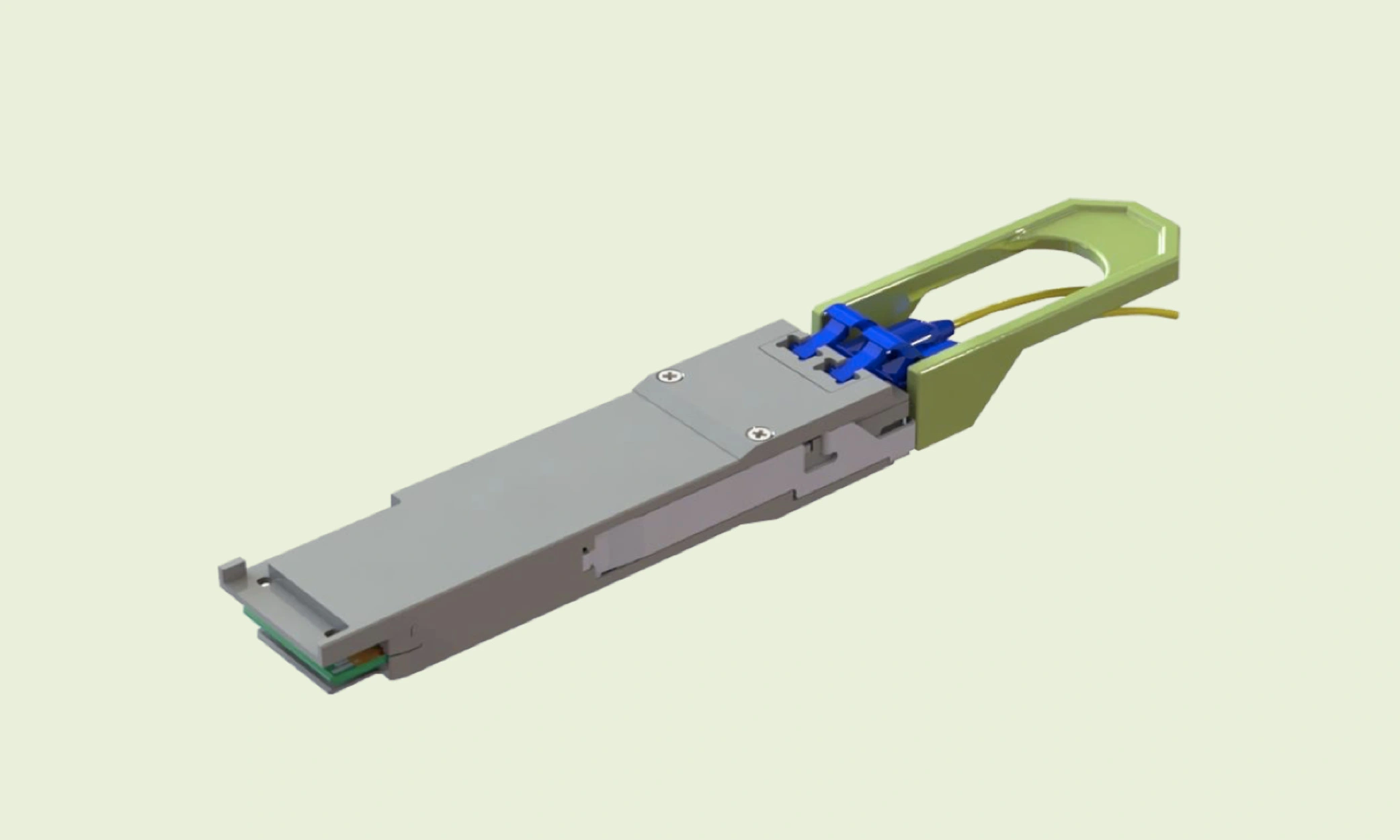
The 100G parallel transmission mode defined by the 802.3ba standard includes two types: 10x10Gbps parallel transmission and 4x25Gbps parallel transmission. The 10×10 Gbps transmission mode is mainly used in the short-distance 100G local area network, and the 4×25 Gbps transmission mode can be used in the metropolitan area network with a longer transmission distance. Among them, the advantages of the 10x10Gbps transmission mode are: the required device rate is low, the existing 10G optical module technology can be used, the cost is low, and the system dispersion capacity is large; Manage maintenance. Relatively speaking, the small number of channels of 4x25Gbps simplifies the optical transceiver structure, which is beneficial to management and maintenance, and the low channel rate of 25Gbps for a single wavelength reduces the difficulty and cost of the device fabrication process. Therefore, the 100G LR4 optical module using the 4x25Gbps transmission mode is the most efficient 100G optical module tW at present. Most of the current commercial 100G optical modules are the first generation CFP products with a structure size of 144. 75x82mm wide xl3. 6mm, the power consumption is about 24Wtisj. The size of the designed optical module is too large, which is not conducive to storage and installation, and due to the excessive power consumption, the operating cost of the optical communication system is too high. Therefore, a second-generation CFP optical module CFP2, which meets the CFPMSA protocol, has a smaller size (Ill.6×41.5×17.4mmW, and lower power consumption, will be 100G) Trends in Optical Communication Systems.
According to the function, the inside of the optical module can be divided into two parts: the transmitting end (TX) and the receiving end (RX). The function of the transmitter is to load the high-speed electrical signal on the laser carrier through the laser modulation technology, and transmit it through the optical fiber to realize the photoelectric conversion of the information. In the actual optical communication network, the optical module often needs to transmit the data of the synchronous optical network. Since the synchronous optical network has high timing requirements, in order to reduce the impact of signal jitter on signal sensitivity, usually the optical module will also integrate CDR chips at the transmitting end and the receiving end to realize the shaping and recovery of high-speed electrical signals and optimize the optical module. transmission performance. TOSA integrates laser LD and electro-absorption modulator EAM. LD is a forward bias voltage, and is driven by a constant DC bias current Ibb greater than the threshold current of the laser, the LD works in a constant mode of operation. The output optical power of the laser can be adjusted by controlling the magnitude of the bias current IbiM by the laser driver LDD. The function of the receiver is to separate the signal from the optical carrier, that is, to convert the optical information into electrical information. The receiving end includes a photodetector and a receiving end circuit that converts the optical signal into a differential voltage signal. The detector is a device that separates the signal from the optical carrier, that is, performs optical/electrical conversion. The quality of the photodetector element determines the sensitivity of the photoreceiver to a large extent. The sensitivity of the optical receiver, the luminous power of the light source device and the attenuation of the optical fiber together determine the relay distance of the optical fiber communication. The commonly used photodetectors are PIN photodiodes and avalanche photodiodes (APDs).
The above content is written by the R&D staff of QSFPTEK. QSFPTEK offers Best 100G optical transceiver at a cost-effective price. Welcome to contact us.

Top 5 Benefits of Hiring Reliable House Cleaners in Melbourne

How to Remove Personal Data from Data Brokers

Bridging the Gap: Challenges and Solutions for Multilingual Events in KenyaBridging the Gap: Challenges and Solutions for Multilingual Events in Kenya

How to Choose the #1 Ranked Phone Data Service Platform

Affordable Virtual Assistant

Effective WordPress Maintenance and Brand Revamping: Key Strategies for Success

iPhone 15 Pro Max Price in Pakistan: A Comprehensive Review

Exotic Escapes: Unveiling the Most Exclusive Villas in North Goa

Earn Profits with Ellyx P2P Cryptocurrency Exchange

Top Small Business Bank Accounts in the UK: Find Your Perfect Fit Today
-

 Blog1 year ago
MyCSULB: Login to CSULB Student and Employee Portal – MyCSULB 2023
-

 Android App3 years ago
Cqatest App What is It
-

 Android1 year ago
What Is content://com.android.browser.home/ All About in 2023? Set Up content com android browser home
-

 Software2 years ago
A Guide For Better Cybersecurity & Data Protection For Your Devices
-
Latest News2 years ago
Soap2day Similar Sites And Alternatives To Watch Free Movies
-
Android2 years ago
What is OMACP And How To Remove It? Easy Guide OMACP 2022
-
Android3 years ago
What is org.codeaurora.snapcam?
-
Business2 years ago
Know Your Business (KYB) Process – Critical Component For Partnerships